DL9KRとのEME交信に成功した時のパワーアンプは4F15Rシングルであった。その飽和出力は100W程度であり、本格的な運用には全く力不足。そこでDick
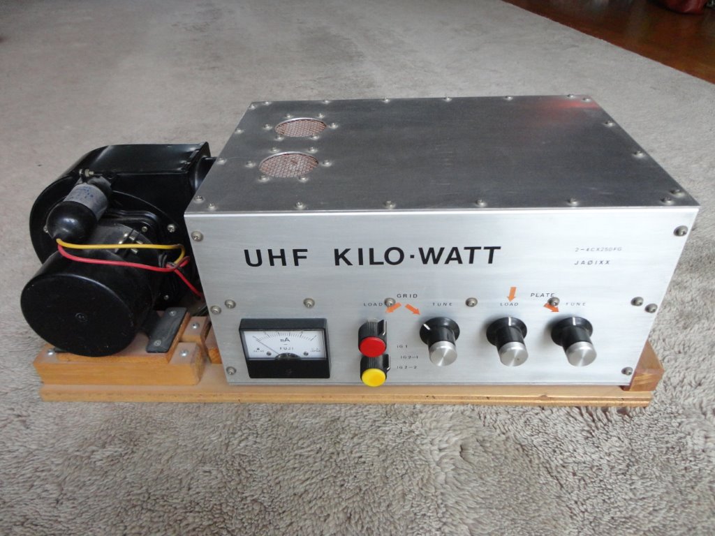
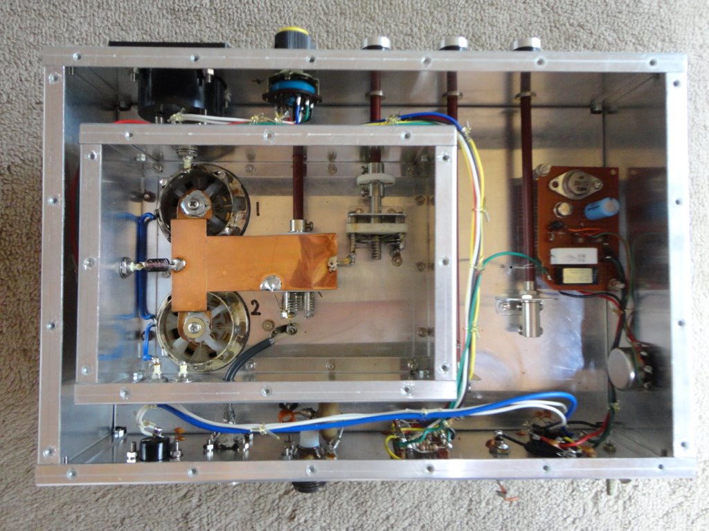
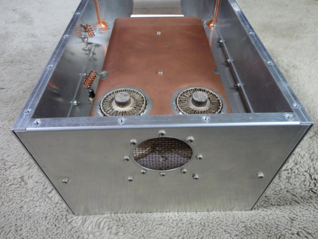
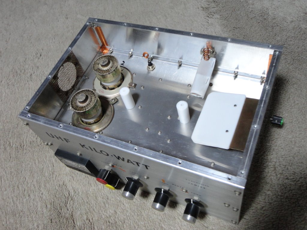
Knadle/K2RIWが発表した4CX250パラレルのアンプを作ることにした。QST誌記事のデータを基に製作を進め、プレート側ストリップラインの長さ以外はオリジナル図面と同じである。第一グリッドの電源はシャントレギュレータに、スクリーングリッド用にはシリーズレギュレータを作り、ブリーダ抵抗を付けた。完成後の調整において、出力は400W止まりでどうしてもそれ以上伸びない。その原因を発見するまで約二週間を費やした。ポイントは結局真空管だった。中古の球をあれこれ入れ替えて試したがどれも今一つ。JA1AUH後藤さんに送ってもらった新品の4CX250FGに交換したら即座に600Wを超える出力を得た。その後、自作トランスバータとこのアンプの組合せにより430MHz帯の500W免許を得ている。(製作は1985年)
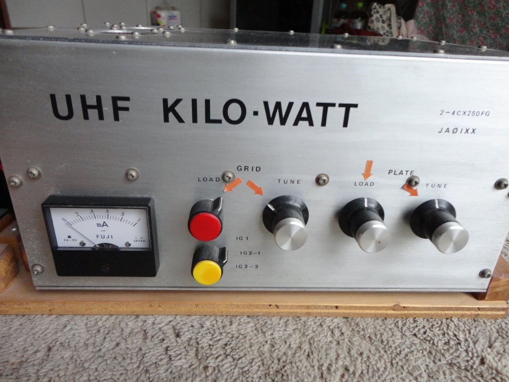
1700V *0.7A Pout 660W (η=56% ) Esg 250V Ig1 20mA Pdrive 16W Gain 16dB on
432MHz
The amplifier was 4F15R single when I succeeded in the EME QSO with DL9KR.
The output power was only 100W and quite dissatisfied for my real operation.
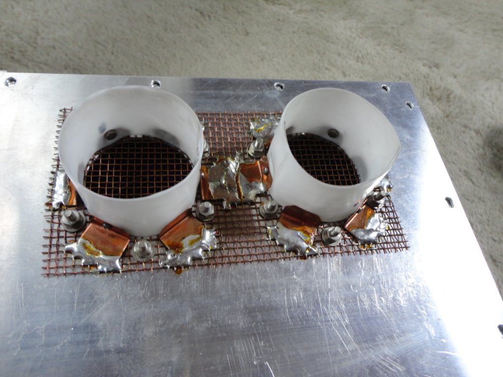
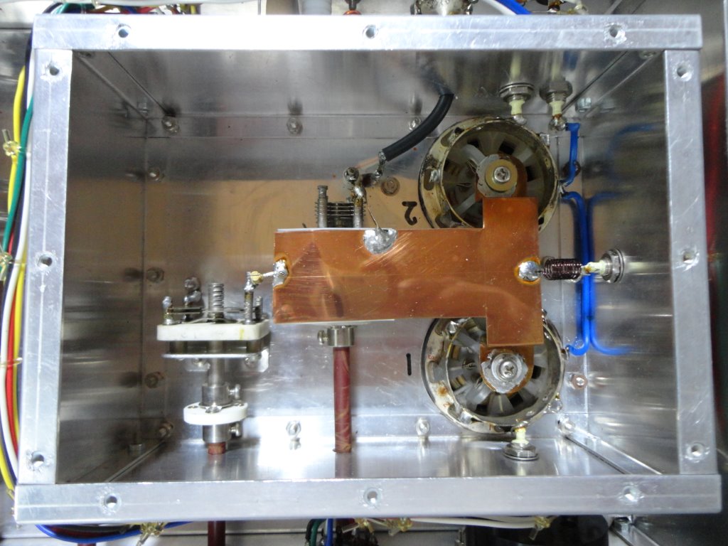
Then, I made the amplifier of parallel 4CX250’s that Dick Knadle/K2RIW
published in the QST 1972. As I advanced making based on the data of QST,
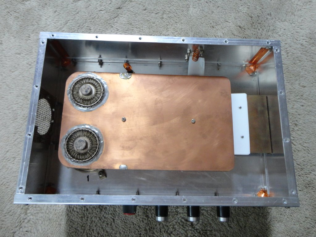
it is the same as an original drawing except the length of the strip line
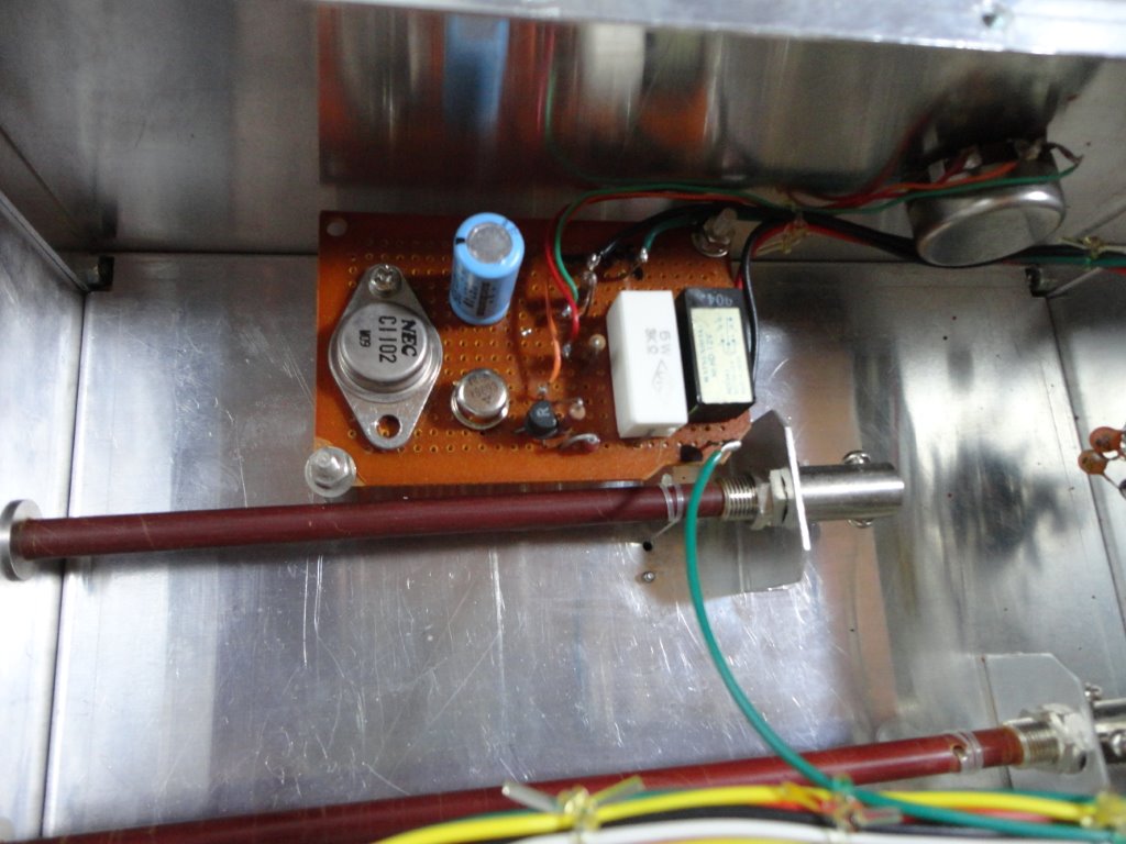
of anode side. The power supply for the first grid was made as a shunt
regulator, and a series regulator was made for the screen grid, and the
bleeder resistance was put. In the first running test, I was disappointed
because only 400W of output was obtained. I wasted two weeks to find the
cause, it was a vacuum tube after all. I replaced and tried used tubes
I owned, but all were insufficient. In the end, the output immediately
exceeded 600W after they were exchanged for new 4CX250FG’s that JA1AUH
sent to me by goodwill. Afterwards, I obtained 500W license of 430MHz EME
with the combination of my home brew transverter and this power amplifier.
(making was in 1985)
1700V *0.7A Pout 660W (η=56% ) Esg 250V Ig1 20mA Pdrive 16W Gain 16dB on
432MHz