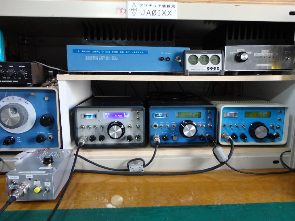
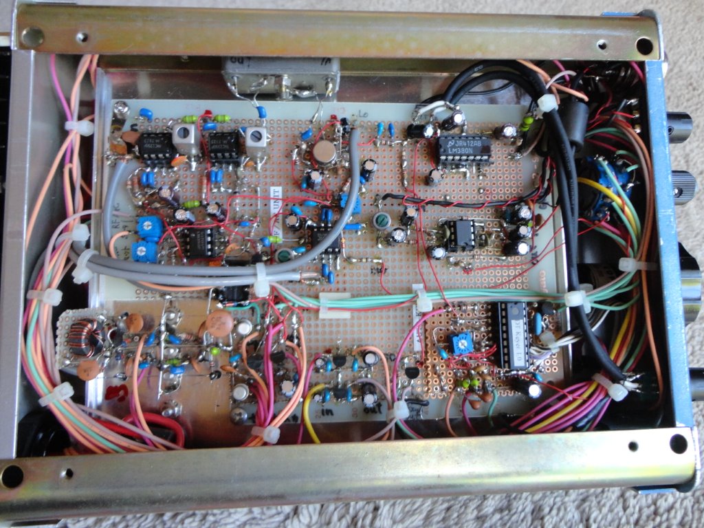
同一パネルデザイン三部作の二つ目は14MHzのSSB/CWである。休日の午前中にこのDXバンドでゆっくりラグチューができるように、シンプルながらも長期の使用に堪えるクオリティの実戦機を作ろうと考えた。構想検討中に、トランスバータを内蔵して50MHzにもオンエアできるようにしたらどうかと思いつき、結局14/50のdual
banderにまとめたもの。心臓部のフィルタはFT201,FT620Bなどに使われた9MHzのクリスタルフィルタである。SSB 2.3kc,
CW(W) 0.8kc の二つを装備し、受信IFampの出口にはこれまた二つめのSSBフィルタが入っている。VFOは7MHzのトランシーバ同様に秋月のDDSユニットを5MHzで動作させている。局発周波数はスプリアス的には23MHzのほうが好ましいのだが、DDSの動作範囲を大きく超えているので諦めた。
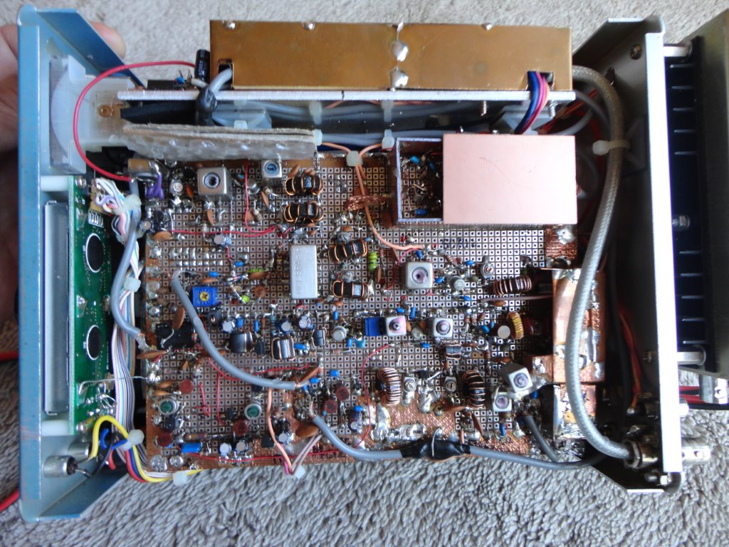
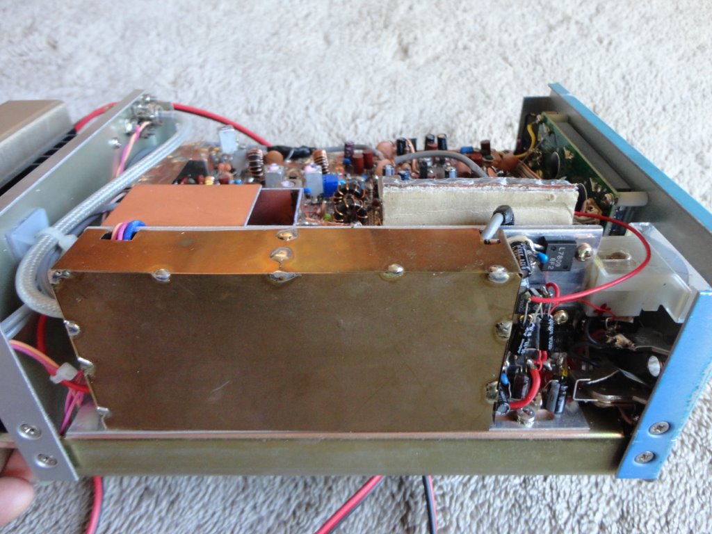
14MHzまでのステージは大きな問題もなく構想通り進んで行き、完成後のテスト交信でも良好なレポートをもらった。困ったのは50MHzだった。+10dBmのレベルまではFBだがドライバーと終段を働かすとひどく歪んでしまう。50MHzのエネルギーが14MHzのステージに回り込み、IMDを引き起こしているのであった。対策として有効だったのは結局シールド。50MHzのDBM以降のストレートアンプは終段まですべてシールドボックスに入れ、ケース内部の引き回しケーブルもRG55U(二重編組)に交換するなどしてようやくおかしなIMDは解消した。エレキーを内蔵し、ブレークインキーイングにしたため、CWオペレーションは至極快適なトランシーバになった一方、SSBラグチュー時のMC1350PのAGCフィールにはやや不満が残るものとなった。詳細はブロック図を参照されたい。2008年製作。
14.000-14.350/50.000-50.5000MHz SSB/CW 10W, S/N≧10dB at-10dBµV(14MHz),
NF2.6dB(50MHz), image ratio≧70dB, DC13.5V & DC28V
Second of the common panel design trilogy is 14MHzSSB/CW transceiver. I
thought I needed a simple but practical machine with high quality which
stands up to long use, and that would offer me a comfortable QSO on this
DX band in a holiday, in the morning. During my planning, I thought of the
new machine that has a built-in transverter in order to QRV on 50MHz, and
it was gathered in dual bander of 14MHz and 50MHz after all. The SSB filter
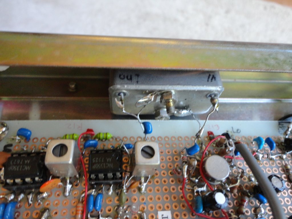
is 9MHz XF92A which was used in Yaesu FT201 FT301and FT620B, and there
is another XF92A between the IF amp MC1350 and the product detector. The
local oscillator is a DDS digital VFO, and the Akizuki DDS unit and JF1DHM’s
PIC IC combination is used again. In the spurious point of view, 23MHz
is more desirable for the local oscillator. But the limited frequency range
of DDS was exceeded big, so it was given up.
There were also no big problems with a stage to 14MHz, and even a test
contact after completion advanced and went as planning, and got a good
report from my local. It was 50MHz that would be a problem. It's no problem
to the level of +10dBm, but when the driver and final worked, the signal
is distorted terribly. It was found that the energy of the 50MHz RF field
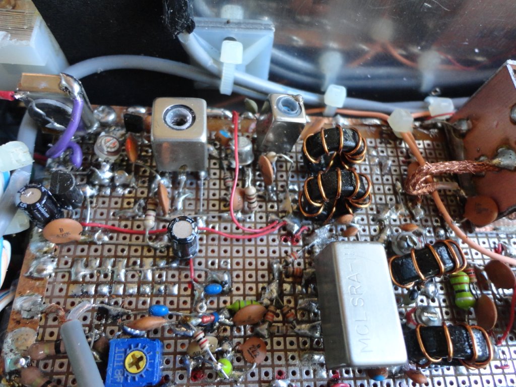
had caused invasion and IMD at the 14MHz stage. It was a shield that is
effective as a countermeasure after all. The 50MHz straight amplifiers
were all put in a shield case, and the coaxial cable for the 50MHz assembly
was changed to RG55U of double shielding, and the harmful phenomenon has
disappeared perfectly. Because it had electric keyer built-in in this set,
and the break-in keying was made possible, CW operation became very comfortable.
On the other hand, it was something which isn't satisfied with an AGC feel
of MC1350P at the time of SSB ragchew little. Please refer to a block diagram
for details. Making was in 2008.
14.000-14.350/50.000-50.5000MHz SSB/CW 10W, S/N≧10dB at-10dBµV(14MHz),
NF2.6dB(50MHz), image ratio≧70dB, DC13.5V & DC28V