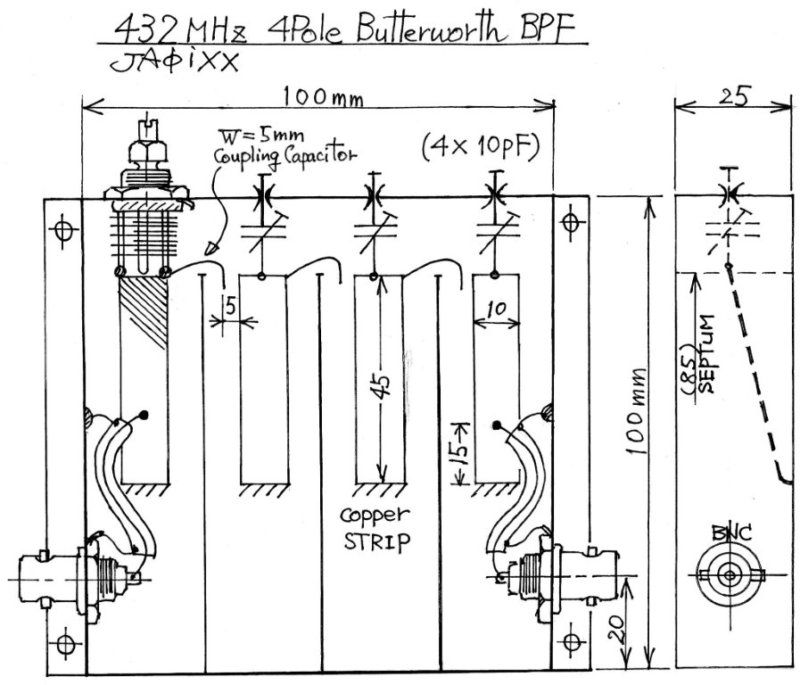
この432MHzの4poleフィルタは、EMEの500W申請時に電監から送信スプリアスのデータを求められた際に、終段の電力増幅器(K2RIW)をドライブするトランスバータの出力をクリーンアップするために製作した。必要とした帯域は432MHz±500kc。スカート特性に切れの良さを求めたが、これは強力なFM局やレピータによる受信時の混変調対策としても有効になると思われたからだ。
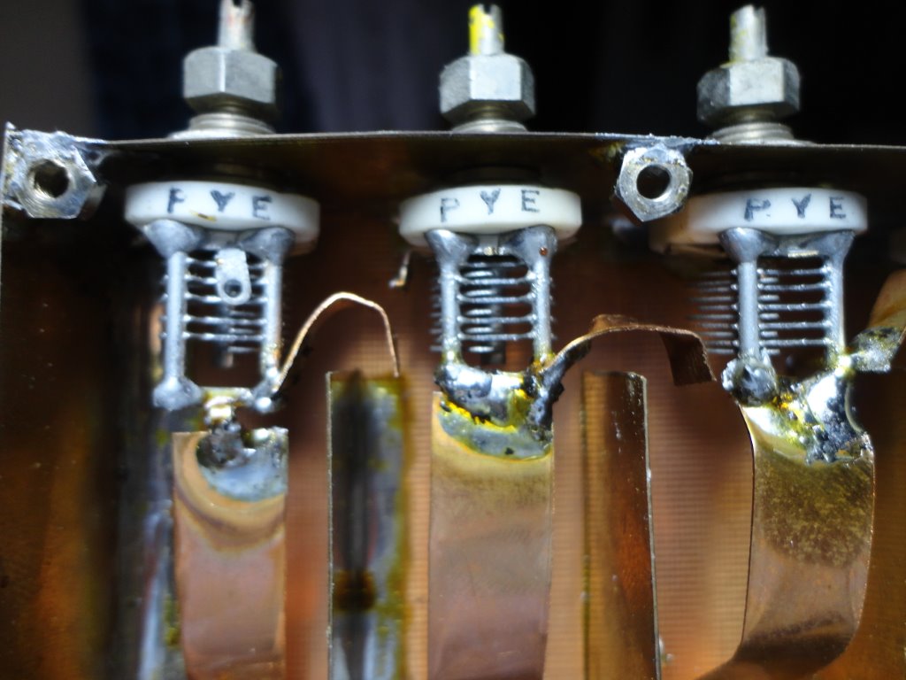
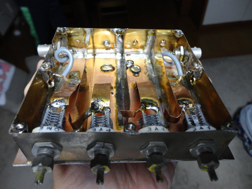
初めは線径2mmのスズめっき銅線を共振棒として使ったが、急峻な特性を得ることができず不満足だった。そこで無負荷Qを最大化できる銅リボンの75Ωラインに変更したところ、期待していた良い共振特性が得られた。共振子の隣接セクションの結合はホットエンドに設けた小さな銅板のベロ(による微小容量)で行なったが、この調整が微妙でVHFまでの機器とは一味違うことを改めて感じさせられた記憶がある。でき上がったフィルタのパスバンド特性は急峻で、バンドエッジで聞こえていたレピータは消感してしまうほど。データを見ると全くスプリアスが見えなくなった。432MHzで通過ロスが6dBほどあるが、トランスバータとドライバアンプ(M57716)の間には元々10dBのATTが入っていたからレベル調整は容易だった。製作は1989年。
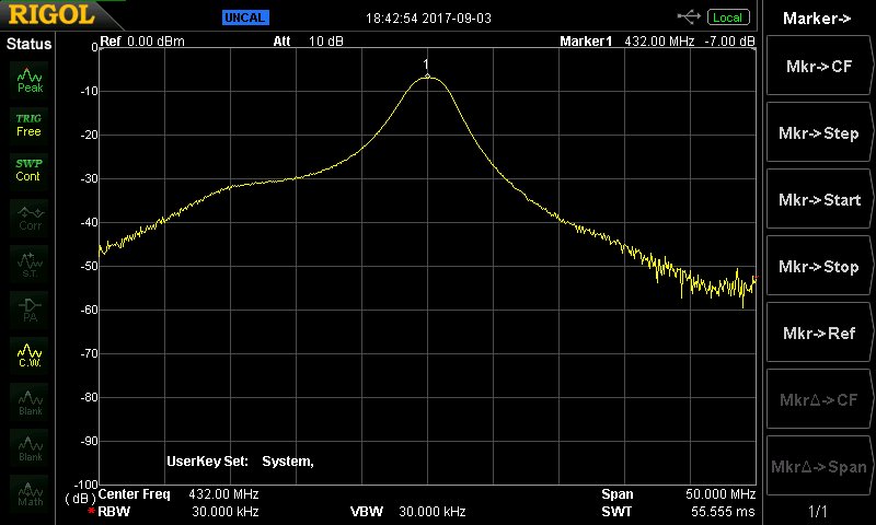
-3dB passband 432±1.5MHz, insertion loss 6.5dB, -20db band width 424MHz
- 437MHz
Some data of the transmitting spectrum was requested by the Radio Regulatory
Bureau in Nagano when I applied for 500W license of 432MHz EME. As I knew
that the spurious suppression of my transmitter was not perfect, then I
made this filter soon to get a clean 20 Watts to drive the final power
amplifier of K2RIW. The passband that I needed was 432MHz±500kc, and steepness
was necessary. It’s because I believed that a good BPF contribute not only
to a clean spectrum of transmitter, but also to the improvement of receiving
capability in the cross-modulation point of view.
First a copper wire of 2mm dia. was used as a resonance element, but it
wasn't possible to get a steep resonation and I was not satisfied. After
all, the expected good resonation was obtained in case of adopting 75 Ω
line of the copper strip which can maximize the unloaded Q. An electrical
coupling of an adjacent resonator is done with a small copper tongue at
the hot end, and I remember the setting and the adjustment was rather critical
than a 144MHz BPF. The pass band of the completed filter was narrow and
steep enough. It was very good to know the signal of FM repeater of my
local has disappeared, which was coming through on the band edge till then.
(The data which was taken recently shows that there is more than 30dB of
attenuation on 439MHz.) The spurious signal really disappeared in the output
of my transverter as expected. Though there were 6dB of insertion loss
on 432MHz, the level adjustment was easy because there was originally ATT
of 10dB being set between my transverter and the driving amplifier (M57716).
Making was in 1989.
-3dB passband 432±1.5MHz, insertion loss 6.5dB, -20db band width 424MHz
- 437MHz