特性の優れたラダー型クリスタルフィルタを作るには、水晶振動子のモーションパラメータを正確に知る必要がある。方法としては、素子の直列共振周波数(Fs)とその3dBバンド幅を測り、計算でパラメータを求めるのが直接的で良い。今までは50Ω系で直接測っていたが、もっと低いインピーダンス環境にした方が測定誤差は小さくなる。(理由は水晶振動子の持つ等価損失抵抗が数Ω~10数Ωと小さいため。)
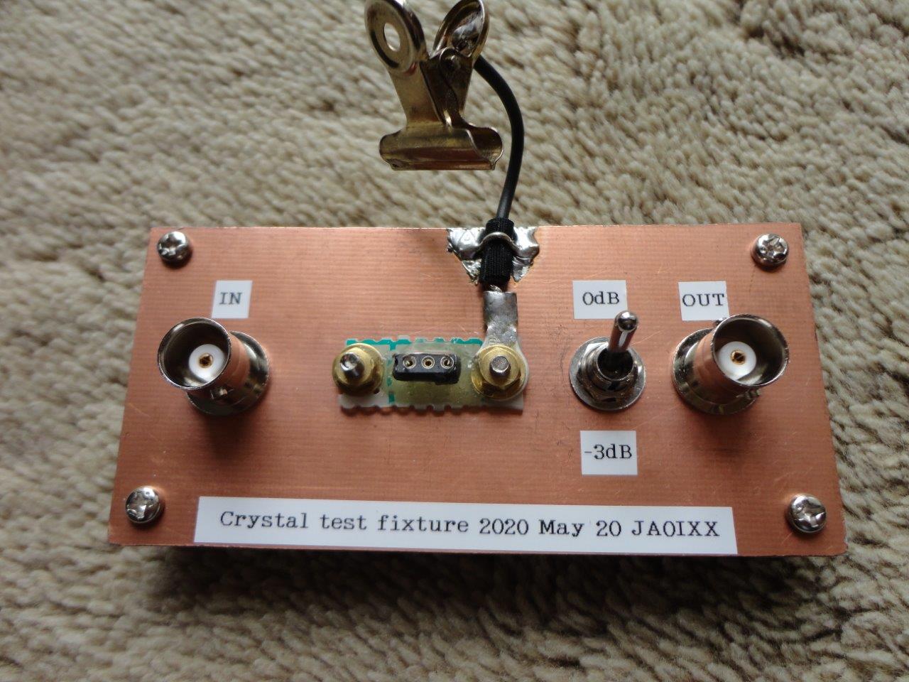
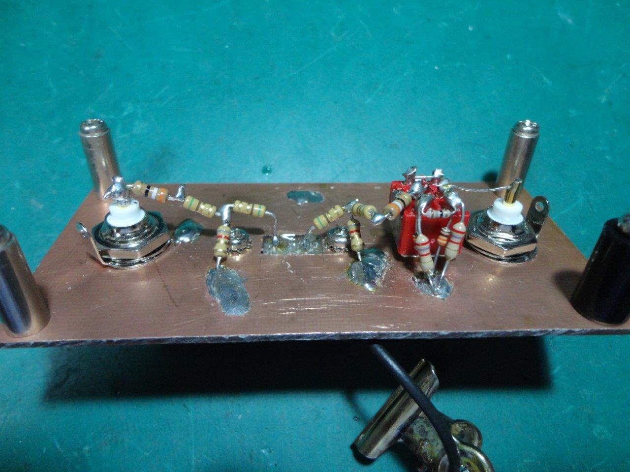
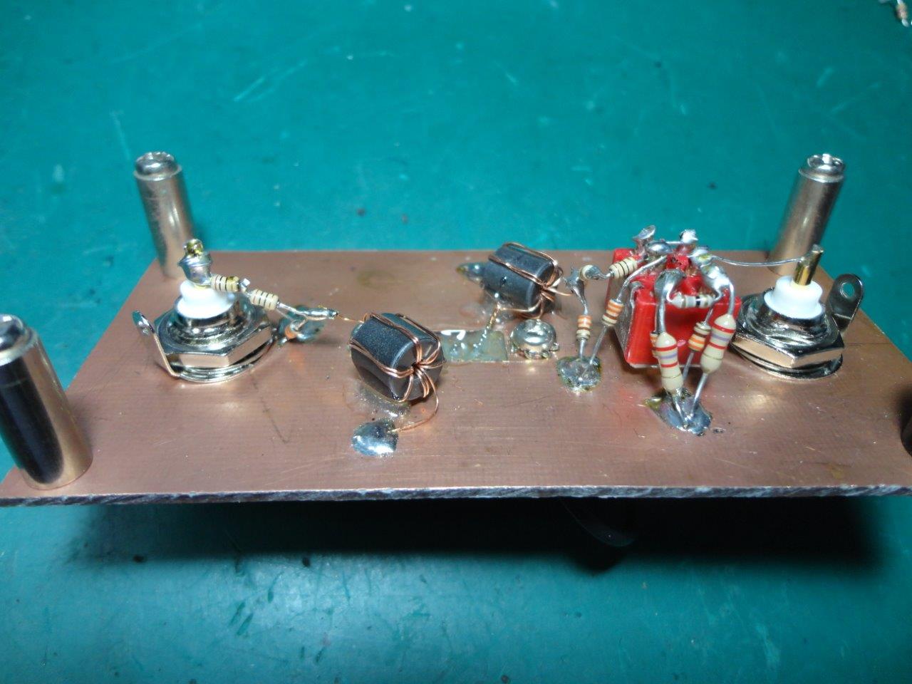
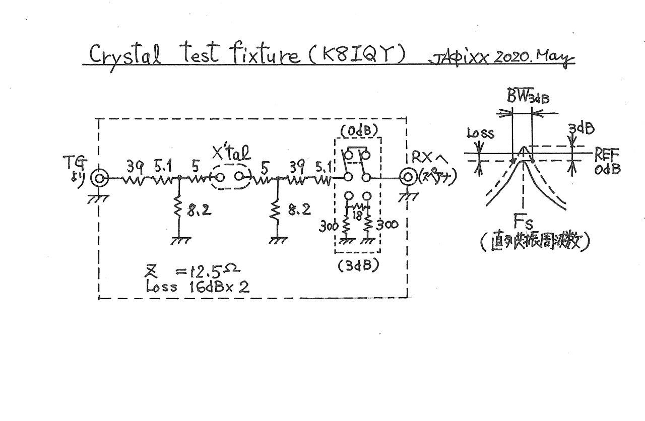
ここに展示するシンプルな治具はK8IQYの資料に基づいて作ったもので、一対の50→12.5Ωの変換パッドとスルー可能な3dB ATTで構成されている。初めは4:1の伝送線路トランスを使ったが、9MHzや12.8MHzでは良い精度の測定結果を得た一方で、4MHzでの測定誤差が8%ほど大きくなってしまった。どうもトランスの作りに問題があったようで、低い周波数帯では正確に12.5Ωのインピーダンスにならず、やや高め(13.5~14Ω)
になっている模様。結局、損失は多いけれど周波数特性の良い抵抗パッド方式に落ち着いた。
①入力にTG、出力にスペアナをつないでシステムを立ち上げ、水晶振動子の端子をジャンパーで短絡した状態でキャリブレーションをとる。(この時3dB
ATT S/Wは3dB側にしておく)
②水晶振動子を取り付け、Fs(直列共振周波数)と挿入ロス(dB)を測定する。次にATTS/Wを0dBに切換え、先ほど測った挿入ロスと同一のレベルを示す上下の周波数を記録し、ΔF(3dBバンド幅)を求める。
③その結果をDJ6EVのラダーフィルタ計算ソフト“DISHAL”の3dB-methodルーチンに入力し、モーションパラメータLm、Cmと等価抵抗Rs、Qu(無負荷Q)を求める。(以上は手計算で求めても勿論良い)
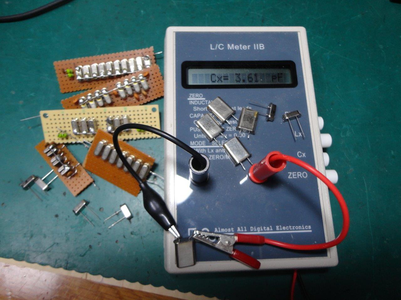
④別途容量計を用いて振動子の極板間容量C0を測定する。
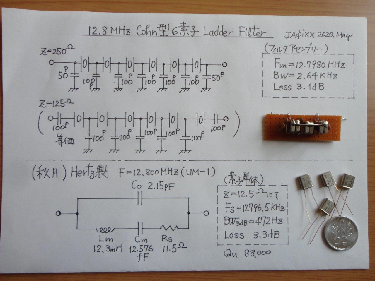
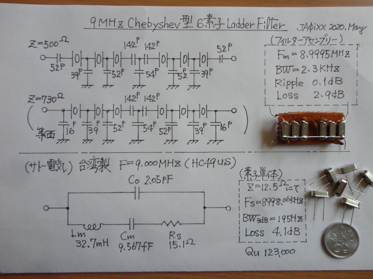
⑤“DISHAL”で計算可能な各フィルタータイプ(Cohn型、QER型、Chebyshev型、Butterworth型)の計算ルーチンに応じ、目的のバンド幅や水晶素子数などとともに測定で得たパラメータを入力し、フィルタの装荷容量(シャントキャパシタ、シリーズキャパシタ)を計算させる。
⑥実測値を基に計算したFsとQuを見ながら水晶振動子を選別する。Fsのバラツキは100Hz以内が目安、無負荷Qは特に値の小さなものをスクリーニングする。
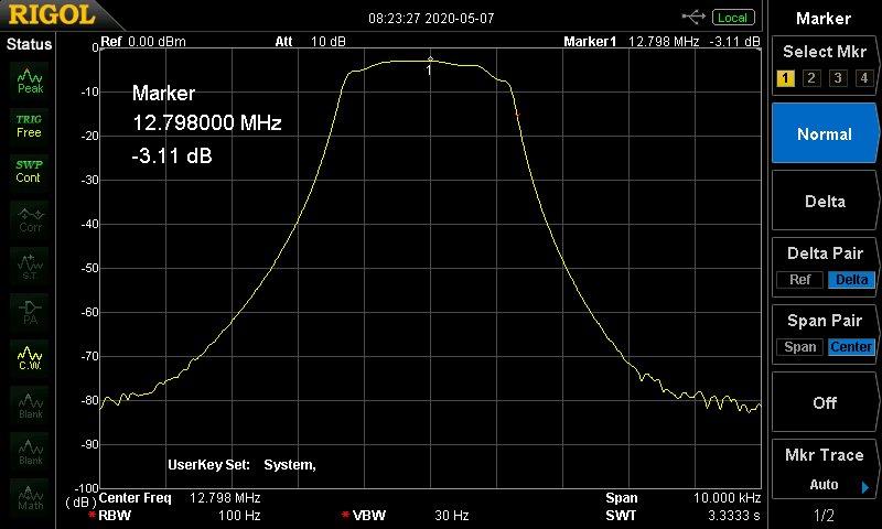
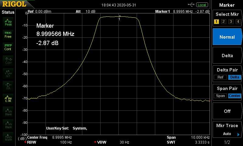
実際にこの治具を使って測定し、そのデータを基に製作したフィルタの事例を添付するが、カットアンドトライ無しに狙いのパスバンド特性が再現良く得られ、とても重宝している。2020年製作。
Crystal test fixture, Z(I/O)=50Ω, Load impedance of crystal=12.5Ω,Insertion
loss=32dB, Useful frequency range is not precisely evaluated yet.
If you want to make an excellent ladder type of crystal filter for your
new homebuilt rig, you had better measure the crystal to know its own motion
parameter correctly. After you measure a series resonant frequency (Fs)
and its 3dB bandwidth, it's easy to get a motion parameter by calculation.
I’ve been measuring them directly with my 50Ω impedance system for years,
but lower impedance environment is actually desirable to make measurement
error at a minimum. It’s because the equivalent loss resistance of a crystal
is very small.
The jig exhibited here was manufactured according to K8IQY's data, which
consists of a pair of 50Ω ->12.5 Ω impedance pads and a switchable 3dB
ATT. Before that, the 4:1 RF transformer was tried, and the performance
was good on 9MHz and 12.8MHz, but measurement error increased up to 8%
on 4MHz. It means the impedance is not correctly 12.5 Ω but 13.5 to 14.0
Ω, so I stopped to use it. (The inductance of the bifilar trans. (six turns
on a ferrite core) seemed to be not enough for low frequency use below
5MHz)
Guidance of how to use this test fixture is omitted. I think it’s also
unnecessary to show the actual procedure to calculate the motion parameters
and the shunt or series capacitance of each type (Cohn, QER, Chebyshev,
Butterworth) with the help of DJ6EV "DISHAL" software. Here I
would like to show you a couple of filter samples which I manufactured
recently. A very good passband quality is obtained without any “cut and
try “process, and is reproducible. Therefore, I think this method is practical
enough and useful for homebrew amateurs. Making is in 2020.
Crystal test fixture, Z(I/O) =50Ω, Load impedance of crystal =12.5Ω, Insertion
loss=32dB, Useful frequency range is not precisely evaluated yet.